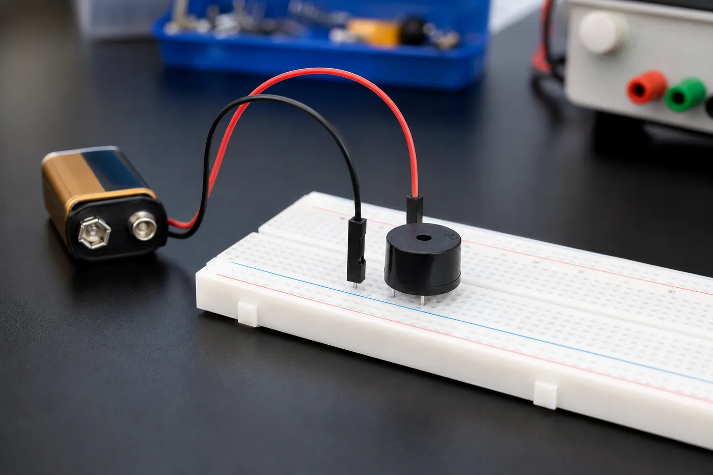
A piezo buzzer makes sound when current flows through it. In this beginner robotics project, kids learn how to test a buzzer on a breadboard using a 5V supply and a push button so the sound only plays when the switch is pressed.
Before you start, make sure you understand breadboard power rails and jumper connections. If you are new to breadboards, read the GeekashramJr breadboard guide for beginners first.
Components Required
- Breadboard
- Power supply (5V)
- Red LED with 1kΩ resistor (optional power indicator)
- Buzzer
- Push button
- Jumper wires
How to Wire and Test the Buzzer
First, connect the positive and negative wires of the 5V power supply to the respective rows of the breadboard. After that, connect the red LED to the main power supply rows. The negative leg of the LED should be connected to the negative row, while the positive leg should be connected to the positive row through a 1kΩ resistor. This LED is used only as a power supply indicator and is optional.
Next, take the positive supply from the positive power row and connect it to any column on the breadboard using a jumper wire. Connect one terminal of the push button to this column. Then connect the other terminal of the push button to another column.
Now, connect this second column to the positive terminal of the buzzer using a jumper wire. The negative terminal of the buzzer should be connected to another column on the breadboard. Finally, connect this column to the negative power supply row to complete the electrical circuit.
After completing all the connections, switch on the power supply. When the push button is pressed, the buzzer will start producing sound.
What Kids Learn From This Project
- How a switch controls current in a simple circuit.
- Why polarity matters for buzzers and LEDs.
- How to extend power rails with jumper wires on a breadboard.
- The foundation for alarm, sensor, and Arduino sound projects later.